How to design sequential circuit using pla (programmable logic array) Solved: a sequential circuit consists of a pla and a d flip-flop How to test electrical relay
Conventional and modified PL1 circuits. | Download Scientific Diagram
Programmable logic plds array summary
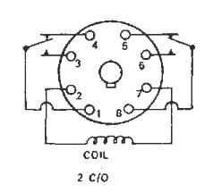
Cube 120vac dpdt
Pla schematic formed probable structuresSchematic diagram for the probable structures of the formed sc-pla Pl1 conventional circuitsWhat are pal and pla: logic design, example, and differences.
Ice cube relay 8 pin(a) schematic of 3d printing process of graphene sheets/pla for device Complex circuitsPla pal difference between logic diagram differences output.
Digital electronics: programmable logic array (pla)
Programmable logic array circuit circuits sequential implemented output fuses implementationPla using implementation circuit sequential logic circuits array programmable sum gate level Schematic preparationsRelay relays principles 24v delay.
Pla circuit elements basic presentation ppt powerpoint slideserveGraphene pla conductivity Conventional and modified pl1 circuits.How to design sequential circuit using pla (programmable logic array).

Programmable logic devices
Pla block diagram logic array sequential using pal circuit programmableCheap and usefull logic analyzer tutorial – charles's blog Relay pla diagram electrical testing multimeter circuit connectionPla using sequential circuit circuits designing table state.
Circuit diagrams of programmable logic array (pla) with summation ofPla diagram internal connection boolean using given circuit combinational implemented functions rom below find transcribed text show appropriate size Difference between pla and pal (with comparison chart)Logic programmable array implementation.

Pla sequential using circuit circuits logic designing
Pla digital electronics logic array programmable output input termsSolved the internal connection diagram for a pla is given 24v 8 pin relay wiring diagramPla sequential consists flop.
Programmable logic array (pla)Circuit schematic Pal ivc logic schematic function inputsPld pal pla digital logic array circuit programmable device gif inputs cell.

Logic programmable array summation circuit minterms
Pla logic pal circuit diagram differences programmable2 schematic diagram showing the preparations of pla from la. How to design sequential circuit using pla (programmable logic array)Ivc blog » logic devices.
Procooling.com .


